Are multifamily buildings one building or a bunch of individual buildings sharing the same structure? Should services and systems be shared or individual? The passions regarding these questions are as strong as those separating Yankee fans and Red Sox fans.
The author is a proponent of the individual buildings and individual services and systems school in addition to being a Red Sox fan. In the author’s world compartmentalization and the Red Sox rule. The most elegant argument for compartmentalization of apartment buildings comes from Handegord (2001).
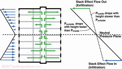
Stack effect driven airflows in tall buildings compromise smoke control and fire safety, adversely affect indoor air quality and comfort as well as increase operating costs for space conditioning energy (Figure 1). By isolating the units from each other and from corridors, shafts, elevators and stairwells stack effect driven interior airflows can be controlled (Figure 2 and Figure 3).

Figure 1: Stack Effect—Interior airflows in tall buildings compromise smoke control, fire safety, indoor air quality, comfort and energy use.
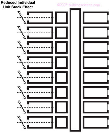
Figure 2: Compartmentalization—Isolation of individual apartment units from corridors and corridors from shafts, elevators and stairwells reduces stack effect driven interior airflows.
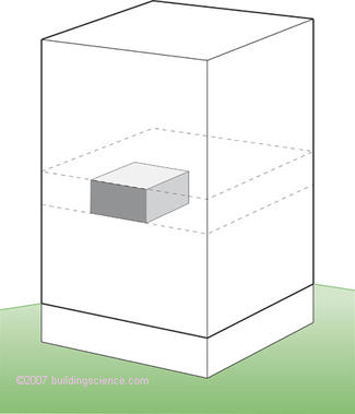
Figure 3: Unit Airtightness—Each unit is isolated from adjacent units and from the exterior by an air barrier system of minimum recommended resistance or air permeance of 2.00 L/(s.m 2 ) @ 75 Pa. The inter-unit separation must also meet the specific fire resistance rating requirement for the given separation.
To achieve compartmentalization unit air tightness should meet a minimum resistance or air permeance of 2.00 L/(s.m 2 ) @ 75 Pa – the recommended minimum resistance of enclosure air barrier systems (Lstiburek, 2005). This level of unit air tightness is necessary to control stack effect air pressures and to limit airflow from adjacent units and cross contamination. Additionally, elevators should be located in vestibules, lobbies and other “airlocks” thereby isolating them from corridors. Unit doors should be weather-stripped.
Applying the compartmentalization principle further, ventilation is provided to each individual unit across exterior walls, not across interior pressure boundaries such as floors. Under the compartmentalization principle ventilation is provided by ventilation systems unique to each unit rather than by central systems (Figure 4).
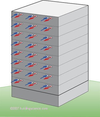
Figure 4: Distributed Ventilation— Individual unit ventilation provided across exterior walls not across interior pressure boundaries such as floors.
In practice roof top central exhaust systems are difficult and arguably impossible to balance and typically defeat measures to control the stack effect through compartmentalization. Balance is complicated due to the additive effect of the stack pressures to the fan pressures in the exhaust system duct risers. Since stack pressures vary with temperature, the flows in the exhaust systems also vary with temperature. The use of constant airflow regulators (devices that maintain constant airflow across variations in air pressure) can mitigate this effect to a degree, but are rarely employed and require extremely high pressures within ducts to effectively operate. Apartments on upper levels tend to be over ventilated during cold weather since they are both closer to the fans and are most subject to the stack pressure.
Shafts acting as exhaust chases or containing exhaust ducts are difficult to seal effectively and significantly complicate fire and smoke control due to the development of complex three dimensional airflow pathways and interstitial pressure fields (Lstiburek, 1998). Ventilation shaft construction is also typically linked to mold and the subject of frequent litigation due to these airflow pathways and the gypsum board used to construct the fire separations (Lstiburek, 1998).
Central systems are further limited as most installations do not allow individual unit control – the central fans are controlled by building management and are typically either on all of the time or off all of the time. Units are either all ventilated or all not ventilated – resulting in over ventilation in many units and significantly higher energy consumption – or under ventilation in many units resulting in contaminant build up and other complaints.
The compartmentalization principle can also be extended to heating, cooling and domestic hot water. Unit space heating is provided by sealed combustion gas furnaces and water heaters located in each individual unit (Photograph 1 and Photograph 2) that are vented either upward or downward through small diameter plastic ducts. Exhaust gases and combustion air are provided by separate ducts that follow parallel paths (Figure 5 and Figure 6). Most systems can be routed upwards or downwards 4 to 5 floors.
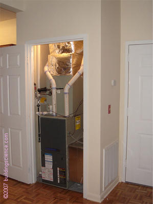
Photograph 1: Space Heating— Sealed combustion gas furnace provides space heating.
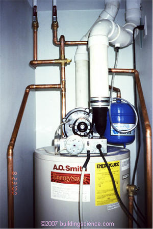
Photograph 2: Domestic Hot Water— Sealed combustion gas water
heater provides domestic hot water.
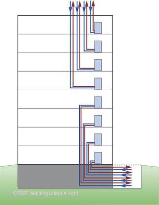
Figure 5: Gas Furnace Venting— Sealed combustion furnaces (two pipe systems – exhaust gases out and combustion air in) are vented to roof or down to dry well (“pit” with screen). Vent runs can extend up or down up to 100 feet.
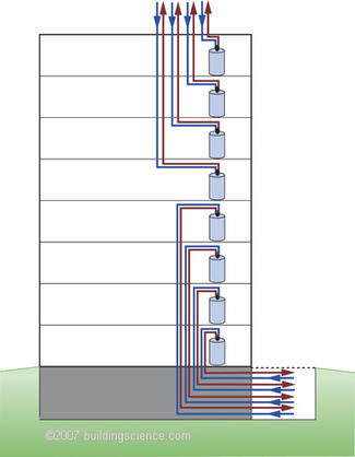
F igure 6: Gas Water Heater Venting— Sealed combustion domestic hot water heaters (two pipe systems – exhaust gases out and combustion air in) are vented to roof or down to dry well (“pit” with screen). Vent runs can extend up or down up 100 feet.
Air conditioning is provided in a similar manner with individual exterior units located on roofs or at ground level in dry wells or in parking garages (Figure 7). Combined heating and cooling with heat pumps is executed in the same manner.
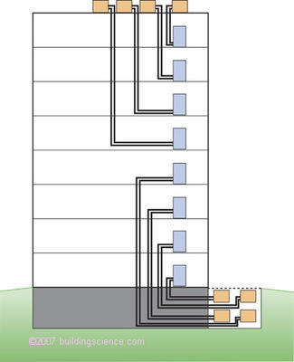
Figure 7: Air Conditioners or Heat Pump Configuration—Individual units are located on roof or in drywell (“pit” with screen).
Rooftop penetrations are collected and located in “doghouses” minimizing penetrations. All cable, duct and pipes are run through walls of “doghouses” (Photograph 3). The “doghouse” lids are removable allowing for access.
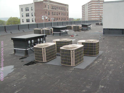
Photograph 3: Services Located on Roof —Rooftop penetrations are collected and located in “doghouses” – all cable, duct and pipes are run through walls of “doghouses.”
The distributed heating, cooling and domestic hot water components are arguably easier to service, and lower in cost to maintain by less skilled personnel than central systems. Problems with systems are limited to individual units rather than many units or entire buildings. Distributed systems are also less expensive to install in many regions. This cost argument is supported on a project per project basis on multi family developments as the free market operates and developers adopt these approaches due to first cost reasons. Developers rarely select systems because they perform better or because they are more energy efficient or because they are safer and provide better indoor air quality – developers select systems because they are cheaper. More of these systems are being adopted and displacing standard approaches principally for cost reasons.
Central systems for heating, cooling and domestic hot water are not conducive to energy conservation since they do not encourage rational individual behavior unless individual metering is provided. It is the author’s experience that individual systems are the easiest to individually meter (Photograph 4 and Photograph 5).
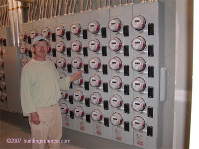
Photograph 4: Individual Metering of Services— Rational behavior is encouraged when all services are metered and billed separately.
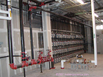
Photograph 5: Individual Gas Metering—Gas for space heating and domestic hot water is separately metered to each individual unit.
In hot humid climates part load humidity control is almost impossible to control with central systems in apartment or condominium construction unless preconditioned make-up air or ventilation air is supplied to corridors through roof-top units. This begs the question whether make up air and ventilation air can be supplied to individual apartments through corridor leakage or door undercuts. Most fire codes do not allow this approach (although in the reading of the codes is not always clear) and require fully ducted supply with smoke dampers. In the distributed conditioning approach individual dehumidifiers are provided in each unit – typically in the air handling closet (Photograph 6).
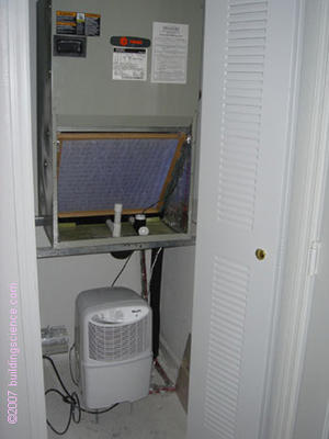
Photograph 6: Part Load Humidity Control—Individual dehumidifiers are provided in each unit – typically in the air handling closet – to handle part load humidity in hot humid climates.
Individual apartment units are in essence treated identically to single family detached houses with respect to heating, cooling and domestic hot water right down to the types of equipment used. Since these systems are for all practical purposes “residential systems” they can be installed by less skilled “residential contractors” – also a huge attractive feature to developers as more sub contractors are now capable of both installation and service.
Ventilation of individual apartment units or condominium units using the compartmentalization approach should be provided according to ASHRAE Standard 62.2, Ventilation and Acceptable Indoor Air Quality in Low-Rise Residential Buildings. In the authors opinion the title of the standard is misleading and limiting as the authors believes that the standard should also apply to apartments and condominiums regardless of height (low rise or mid rise or high rise).
The author’s preferred system configuration is presented in Figure 8. An outside air duct is directly connected to the return side of an air handling unit. An inline motorized damper and the air handler blower is controlled by a programmable thermostat or other device to ensure minimum ventilation and to prevent over ventilation. Exhaust air is vented directly to the exterior from the kitchen and bath via an intermittently operated fan (or fans) controlled by the occupants. The author further prefers that the exhaust fan (or fans) are controlled by a switch with an integral timer that shuts off the exhaust fan (or fans) after a pre-set time (say 10 minutes) – a practice common in the hotel and hospitality industry.
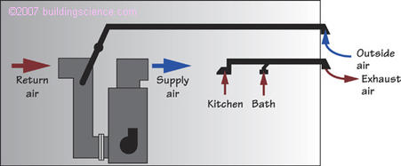
Figure 8: Outside Air To Air Handler— Motorized damper in line with outside air duct connected to return side of air handler. Damper and air handler controlled by programmable thermostat or other controller. Kitchen and bath fans controlled intermittently by occupant.
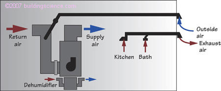
Figure 9: Dehumidifier With Air Handler—Dehumidifier added to control part load humidity in hot humid climates.
Dryers should be vented directly to the exterior (Figure 10). An even better approach, in the author’s opinion, is the use of condensing dryers that require no exterior vent. The water removed from the clothes is condensed and drained – no exhaust to the exterior occurs. This approach has obvious advantages with respect to make-up air (none is needed), and thus provides huge benefits in hot humid climates from latent load perspectives and negative pressures not to mention the benefits in cold climates arising from heat reclaim. In a hot humid climate a 200 cfm exhaust flow results in approximately a 1 ton load. During part load periods the 200 cfm exhaust is almost entirely a latent load dramatically skewing the sensible to latent ratio. And finally there is one less hole in the building enclosure to worry about.
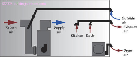
Figure 10: Dryer— Dryer vented directly to exterior. Ventless condensing dryers are preferred.
Not all apartment units or condominium units are designed and constructed with air handling units. Many units have electric heat and no air conditioning – particularly in the Pacific Northwest and others have through wall packaged heat pumps that provide both heating and cooling. Figure 11 and Figure 12 illustrate the compartmentalization approach for such units.
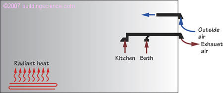
Figure 11: Exhaust With Outside Air Duct— Not the best approach as it relies on “induced infiltration” – the air exhausted will be replaced by infiltration air through the duct. Works best with effective compartmentalization (unit air tightness should meet a minimum resistance or air permeance of 2.00 L/(s.m 2 ) @ 75 Pa).
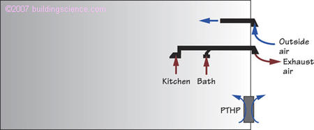
Figure 12: Exhaust With Outside Air Duct – PTHP: Similar to Figure 11, but with air conditioning added via packaged heat pump.
Exhaust is provided by continuously operating exhaust fan with outside air (“make-up” air) provided by an outside air duct. In the authors opinion this is not the best approach as it relies on “induced infiltration” – the air exhausted will be replaced by infiltration air through the duct. In the authors experience this approach works best with effective compartmentalization (unit air tightness should meet a minimum resistance or air permeance of 2.00 L/(s.m 2 ) @ 75 Pa) thereby limiting air drawn from neighboring units and the corridor and thusly favoring the outside air duct as a source of “make-up” air.
A better approach is presented in Figure 13 where both supply and exhaust of air is provided by a heat exchange ventilator. The installed cost of this approach is significantly more than the approaches described in Figure 11 and Figure 12. But the approach has the benefits of lower operating costs (in many climates – particularly extreme climates such as severe cold and hot humid) and not relying on “induced infiltration.”
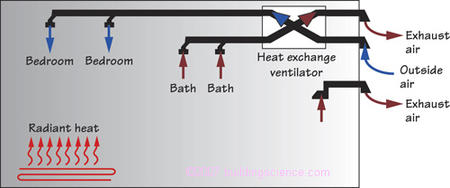
Figure 13: Heat Exchange Ventilator—E xpensive to install, economical to operate.
Compartmentalization of the building enclosure and apartment units and condominium units to control stack effect driven interior airflows can be extended to ventilation systems and systems for heating, cooling and domestic hot water. The approach results in distributed systems that allow for individual unit control, service, replacement and metering.
The approach arguably results in buildings that are safer from a smoke and fire perspective, buildings that are more energy efficient, more comfortable and more durable with better indoor air quality.
ASHRAE Standard 62.2 – 2004, Ventilation and Acceptable Indoor Air Quality in Low-Rise Residential Buildings .
Handegord, G.O. “A New Approach to Ventilation of High Rise Apartments.” Proceedings of the Eighth Conference on Building Science and Technology , Ontario Building Envelope Council, Toronto, Ontario, February, 2001.
Lstiburek, J.W. “The Pressure Response of Buildings.” Thermal VII, ASHRAE/DOE/BTECC , December 1998.
Lstiburek, J.W. “Understanding Air Barriers.” ASHRAE Journal , July 2005.